搬运于:Sprites mods - Miniature Macintosh Plus - Intro
最开始是在B站刷到了一个视频,感叹于作者的还原度,于是翻到了这篇博客
Intro
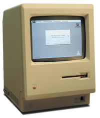
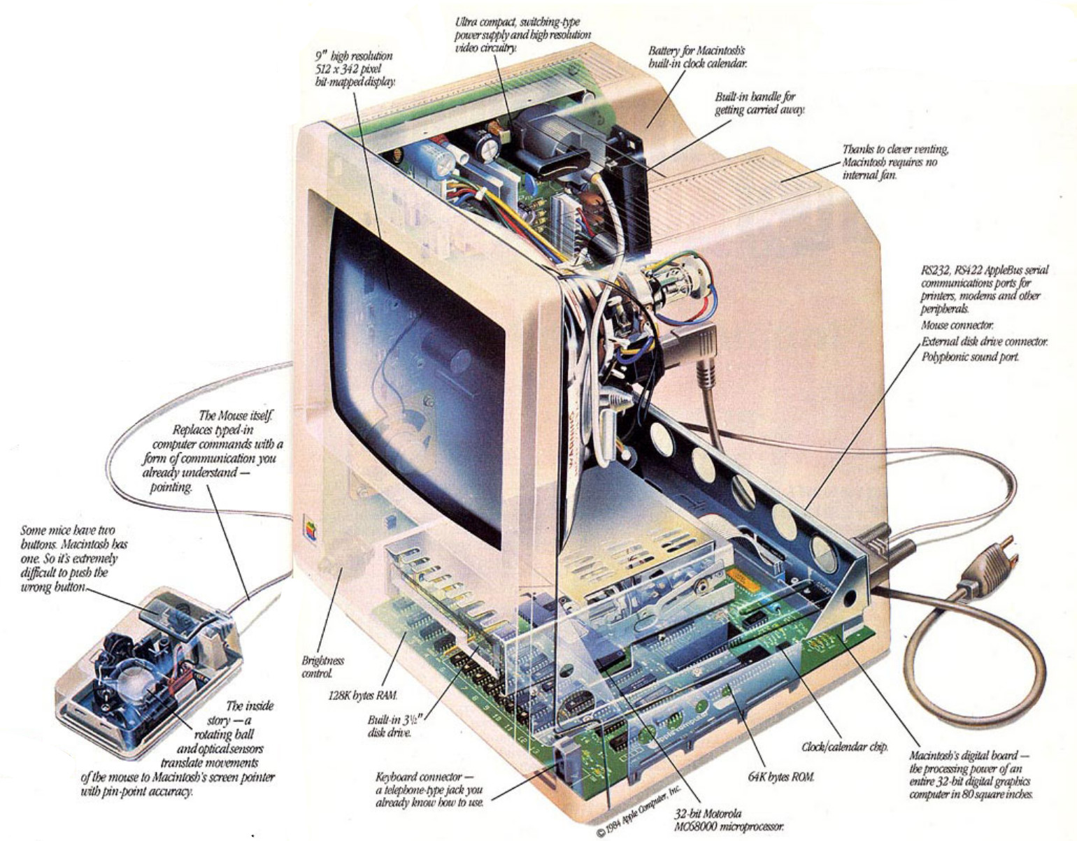
Back in the early days of computing, there was a company called Apple. They just had great success with their Apple II line of computers, but needed to innovate to stay on top of the quickly-developing computer scene. They already were working on the Lisa line of computers, a minicomputer-inspired beast intended for business users and priced as such, but that was deemed too expensive for the average customer. As a secondary project, the Macintosh was developed, initially with the idea in mind to make a new generation of computer for ‘the man on the street’ which should cost about $500. Steve Jobs got put on the project, and under him the hardware got more advanced,the software got a GUI instead of a text interface, and the price ballooned into almost $2500. Although the hardware you got for this price was slightly underwhelming, lacking e.g. the graphics accelerators and hardware sound capabilities other machines had, the software made more than up for it. This first Macintosh was the Mac 128K and its succes spurned more advanced models of this compact Mac, namely the Macintosh 512K, the Macintosh Plus, and the Macintosh SE-series.
While the development of the Macintosh happened around 1984, way before I was at an age I could understand computers, I do feel some kind of kinship with the compact Macintosh: the first computer my parents owned was a Macintosh Plus. It was later joined by a 20MB SCSI hard disk, and on that machine I wrote my first Basic-programs. Back when I still lived in the Netherlands, I actually bought a broken SE/30 machine and converted that into a Linux-server while still being able to run Mac-software. I left that machine in the Netherlands, however, and here in Shanghai, I have no classic Apple hardware anymore.
While obviously I don’t really need a Mac Plus anymore for my day-to-day life, I did like the idea of having one available for when I felt nostalgic. Maybe I could get a tiny bit of the Macintosh experience back by building a small one myself. Seeing I already have some experience with making smaller versions of old hardware, why not try to apply that process to the venerable Mac Plus as well?
Display
So, what to use when building something like this? One of the ways that sprung to mind was to take a Raspberry Pi or something, add a 2.5" LCD, add an emulator like PCE or MiniVMac, 3d-print an enclosure and call it a day. But I didn’t feel that would do my idea justice: not only would it be too big for my tastes, it also would be too easy: With the original Mac 128K, even while the end result was seen as underpowered, the hardware designers that built it did their best to pull a few nice tricks to save cost. Just assembling off-the-shelf commodity hardware into a replica felt like I would be doing the original design a disservice. So off to Taobao for some more exotic components I went!
I decided to start with the display. The Mac had a fairly high-resolution display for its time, and finding a display to replicate that had a pretty high priority. In general, when it comes to displays available on the Chinese electronic market, there’s a large choice available. Unfortunately, the ‘large choice’ seems to consist of either higher-resolution but larger screens, or alternatively tiny but lower-resolution screens. Ideally, I needed a resolution of 512x342 pixels; that is the native Mac resolution and on a screen like that, I would be able to display everything without rescaling. Unfortunately, screens with this resolution don’t readily exist; the next best resolution up would be something like 640x480. Screens with that resolution, for some reason, tend to start out pretty big: the smallest viable one I could find was about 3.5". So unfortunately, I would have to do some downscaling if I wanted to make the Mac as small as possible.
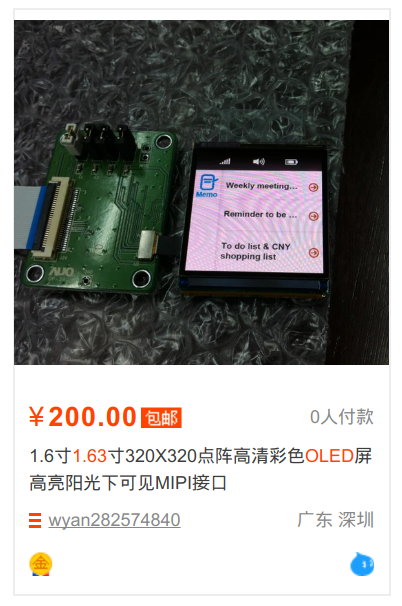
After deciding it would be okay to downscale a bit, I had access to a fair amount more displays. One of the displays that popped up pretty quickly was the x163qln01, an 1.63" OLED screen made by AUO. While slightly expensive (about US$25 per screen), this display has good availability on Taobao and a datasheet that at least documents the pinouts, dimensions and power source requirements. This display seems to be made for certain Android smartwatches, and with some mangling of search terms, Google even spat out some initialization sequences I could use.
The only problem (well, aside from the connector that had pins a mere 0.5mm apart) was that the display did not use a parallel or SPI interface, but a MIPI interface. I’d have to tackle that later on.
With the choice of display made, I could move on to the processor. I grabbed an ESP32-Wrover module for this. This module contains an ESP32 (a WiFi chip with 2 32-bit CPUs running at 240MHz and about half a megabyte of RAM), 4MiB of flash and 4MiB of PSRAM memory. My guess was that the 2 CPU cores would be fast enough to emulate a Mac and that I could use the 4MiB of PSRAM memory to give the Mac its RAM. While 4MiB of flash is not that much, it should be enough for the emulator plus a small-ish hard disk with the system software and some programs. Also, it helps that I work for Espressif, making me pretty familiar with the hardware; what also helped was that I could just grab some modules from work instead of having to buy them and then wait for them to arrive.
With that, I was mostly set - the OLED still needed some components to be powered so the component count was increased by some LDO and other power supply chips. The Mac also needed sound so I sourced a cheap amplifier chip and speaker, and for power and debugging I pulled a common FT232 module out of a drawer somewhere. All these components are pretty small and allow me to scale down the enclosure, resulting in a model that would be a little bit bigger than 1/6th of a real Mac.
Driving the display
While I had nothing to complain about the resolution, size and brightness of the display, actually getting pixels to it was more problematic. The MIPI interface it has was not supported by the ESP32 silicon so I would have to find another way to interface with it. The MIPI DSI interface is a standard developed by the MIPI Alliance and not public; as a hobbyist, I’d have to piece together the details from leaked documents and probing of existing devices. Luckily, a year or two ago Mike Harrison reverse engineered the MIPI DSI interface used to control iPod displays (1, 2, 3, 4, 5, website) and also managed to find some copies of the specifications. This made my life a lot easier: it helps to at least know what to send to the display.
While there is a lot more to it (and you should really watch the above videos if you want to know what), the physical layer of the MIPI protocol is pretty simple to explain. The MIPI protocol uses four wires in total: two data- and two clock-lines. The MIPI protocol has two modes of signalling: Low Power (LP) mode and High Speed (HS) mode.
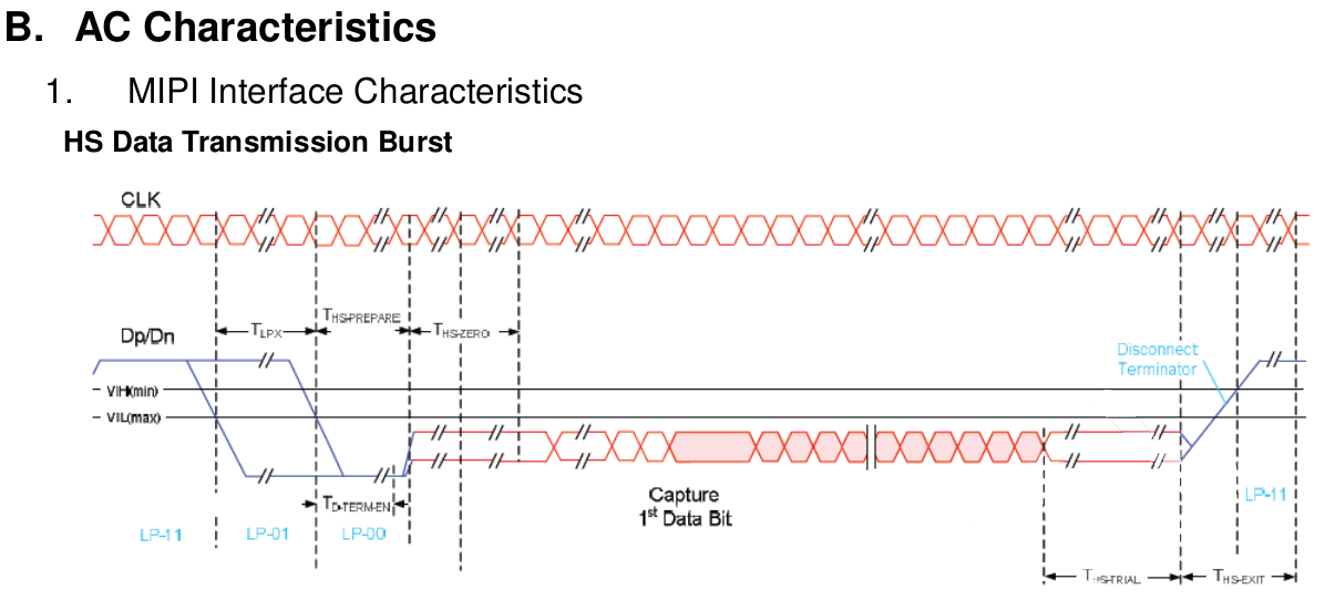
In Low Power mode, the wires are used separately to transmit some control data structures as well as indicate certain commands that have direct effect on the physical receiver on the other side. The voltage swing in this mode is pretty large compared to the high speed mode: voltages are either around 1.2 volt for a high signal, or around 0 volt for a low signal. Because low speed mode has more signal states, it does things like tell the receiver to enter or exit high speed mode. In the diagram above, the blue lines indicate Low Power communication.
In High Speed mode, the two clock lines (CLKP/CLKN) as well as the two data lines (DP/DN) work as differential lines, with one line always being the opposite as the other one. The receiver detects the difference between the two lines, and deduces the value being sent from this: a 1 if DP is higher, a 0 if DN is higher. High-speed mode, as the name implies, allows for very quick data transfers with clocks up to 1.5GHz. The trick the standard used to get this done without too much EMC and power use is to use very low voltages in this mode: the voltages on the pairs average to about 200mV, with variations of +/- 100mV per line to indicate the ones and zeroes. In the above diagram, the red bits are done in high-speed mode.
For the actual data transfer, in high speed mode the interface can essentially be seen as a somewhat weird and differential SPI interface: there is a clock and data path, and every clock tick, the value of the data is clocked into the interface. A change from SPI, apart from the fact that the signals are differential, is that a data bit is clocked in whenever the CLK lines change state, instead of only on e.g raising edges. Another difference is that the start of a transfer is detected not by a /CS line going low, but by in-band signalling: every transmission starts with one unique binary ‘magic word’ and the receiver detects this value to decide when a transmission starts.
In order to interface this with the ESP32, I’d have to do some level shifting. I wanted to run the ESP32 from a 3.0V power source, so all GPIOs would also be 3.0 or 0 volt. To adapt this to the signal levels of the MIPI interface, I opted for the most cheap solution: just use some resistor divider networks.
To figure out the resistor values, I effectively made equations for the three voltage output states that interested me (1.1V for Low Power high, 0.07V for High Speed low, 0.33V for High Speed high; voltages chosen to stay in-spec for most situations) and the three input states that should generate them. Using some math, I ended up at some equations. I could theoreticaly work out those equations by hand, but eventually decided to throw them into WolframAlpha which gave me the needed resistor values.
1 | 3V |
At that time, I figured I could also cheat a bit: because the lines are differential in high-speed mode, the display will only look at the difference between the two lines to deduce the data sent. This means that I can save a GPIO by holding one of the lines at a fixed voltage, making the other line higher and lower as needed. To do this, I needed a second type of resistor network:
1 | 3V |
Another thing to solve was the clocking scheme. Normal SPI clocks in a bit on a raising edge of the clock line. (Or a falling one, depending on the configuration.) MIPI clocks in a bit on both the raising as well as the falling edge of the clock signal. While the ESP32s hardware SPI unit cannot by itself generate a signal like this, we can convert from one to another by using a simple D-type flipflop with its inverted output connected to its input. Every clock pulse on the input will change the level of the output, exactly as is needed here.
Schematic
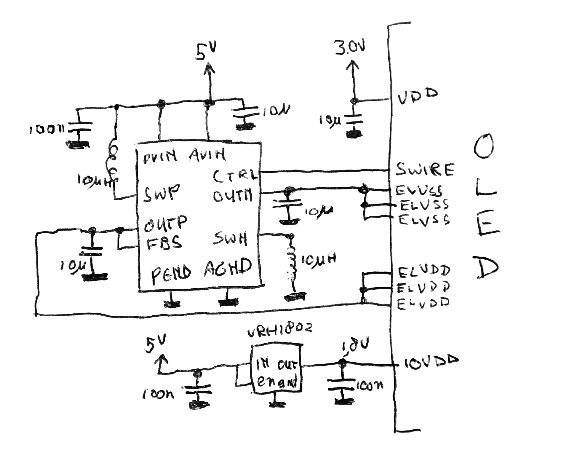
With the display hardware fixed up, the hardest part of the hardware design was done. Now we only need to add the rest. First up, the power supply. This is pretty simple: I feed the entire design from 5V from an USB-to-serial converter that I also can use as a debugging/programming interface. That voltage is taken to generate the +4.6V, -3.4V and 1.8V the OLED screen needs, as well as the 3.0V to feed the ESP32. The +4.6V and -3.4V are generated by a TPS65631 chip, and a reference schematic for that was included in the datasheet for thr OLED. The other voltages are generated by a pair of simple LDOs.
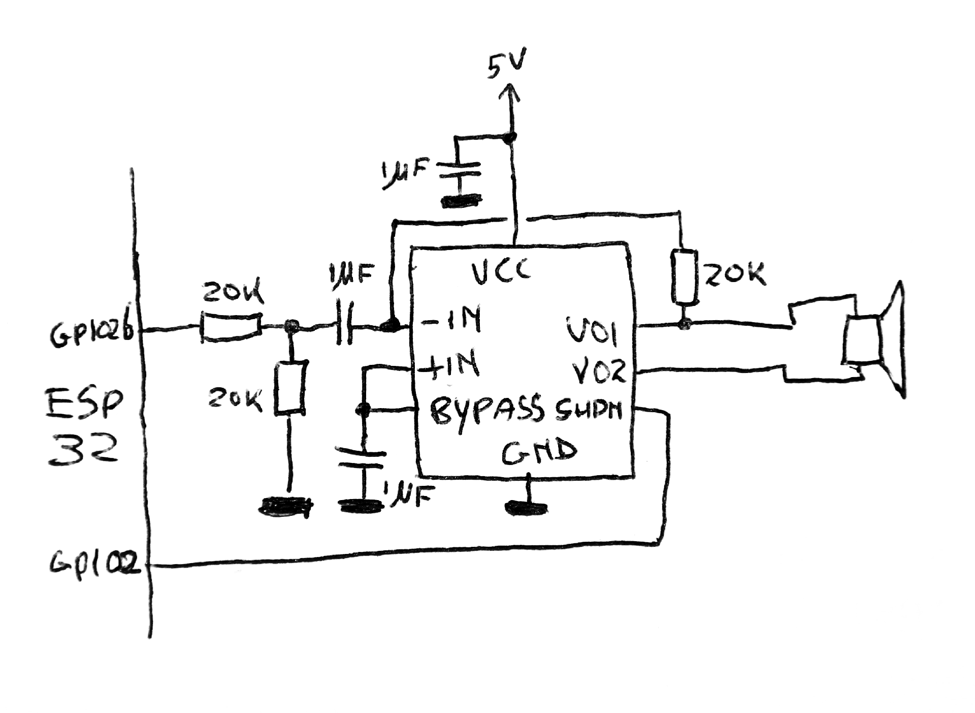
The Macintosh also had sound. The quality isn’t that good by modern standards (22KHz, 8-bit) but the sounds that various software programs make are by now quite iconic, so I couldn’t forego a speaker here. The ESP32 has a built-in 8-bit DAC, and that is used to render the analog soundwaves that the emulator generates. That then gets put into a NS8002 which is a 2W class-AB audio amplifier housed in a small SOIC8 package. It is cheap, needs very few support components and makes more than enough noise for the tiny Mac to attract attention.
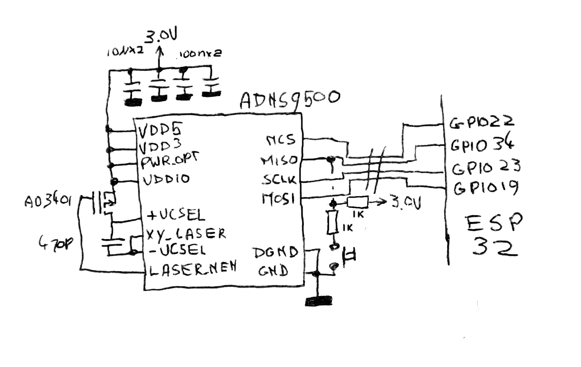
One of the things that made the Macintosh so revolutionary is that it was one of the first commercial computers that came with a mouse. The Macintosh team thought so highly of the mouse that essentially the entire OS is based around mouse-controlled UI elements, and unlike, for example, an IBM PC, it is entirely possible to control the entire Macintosh with only a mouse. Obviously, my tiny Mac should also have such an important peripheral. I still do remember the original ball mouse that came with the early Macintoshes, and I do not quite relish the need to get the gunk off the little rollers every so often; there is a reason optical mice have replaced these mechanical devices entirely. This also has the advantage that parts for these new-fangles optical mice are quite easy to obtain: I did not need to spend much effort at all to locate a source of ADNS9500 gaming mouse sensors plus the corresponding optics, for instance.
The other nice thing is that an optical mouse sensor is a pretty deeply integrated device: a mouse sensor only needs a few other external components to function, and the schematic reflects this. There are a few capacitors for voltage stabilization, an MOSFET (copied straight from the datasheet) to switch the laser diode, and some other jellybean parts. The mouse sensor communicates using a four-wire SPI signal, and I’ve re-used one of these wires to also send the mouse button signal over: the MISO pin is pulled down with a fairly strong pulldown when this button is pressed. The value of this pulldown resistor is not enough to stop the mouse sensor from communicating, but it is enough to overcome the pullup-resistor that normally pulls up the line, so when the sensor tristates the MISO line, the ESP32 can detect if the button is pressed.
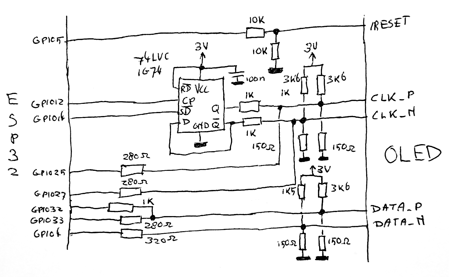
Finally, the OLED screen needs connecting. We already did all the hard work calculating all the resistor values, so the schematic should be more or less self-explanatory. The chip added is a D-type flipflop and is used to halve the clock rate: as mentioned before the MIPI standard needs a new data bit every time the clock polarity inverts, while the ESP32 can only send out a new one on a raising or falling edge.
With the schematic drawn, I moved on to the PCB artwork. The display I chose was meant to be mounted to its controlling PCB, with the connector on the backside of that PCB. While that would not leave much room for the other components, I still wanted to put all the other components on the other side.
![]()
It’s a good thing I have a good pair of eyes and a hot-air rework station: this allowed me to use 0603 components which made everything fit cleanly on the limited PCB space. Especially the connector for the display and the QFN OLED power supply chip would be pretty hard to do with a normal soldering iron.

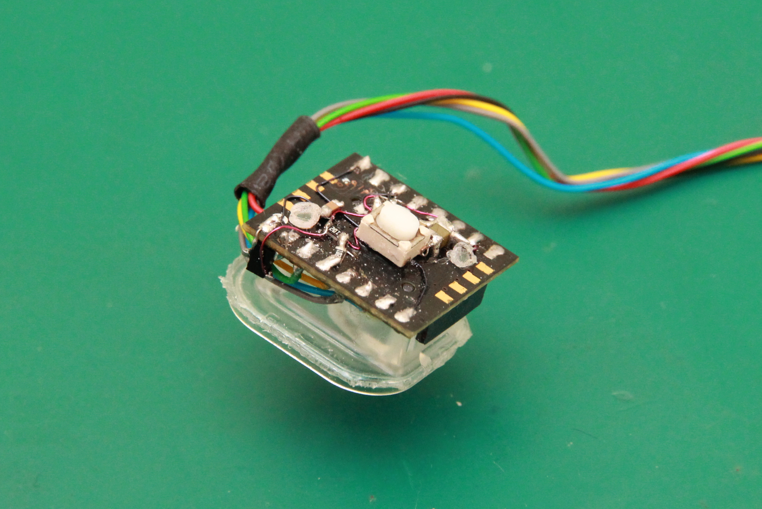
For the mouse sensor and attached components, I figured out using a PCB would use up too much space. Instead, I opted to solder all components on the sensor itself, freeform style. This way, everything should be able to fit in the mouse.
Software
Now obviously, the software is a fairly big element of this build: the entire Macintosh needs to be emulated. The Macintosh, however, is not that complicated a machine. It essentially consists of the 68000 microcontroller, a Zilog Z8530 serial communications controller that controls the serial port, a 6522 VIA for some internal input and output and for interfacing with the keyboard and some random PALs containing the logic for the display and sound. There also is an Integrated Woz Machine-chip to interface with the floppy drive. This is a fairly complicated chip; however I was not planning to emulate a floppy so for emulation it would be enough to emulate an IWM that always returns that there’s no floppy in the drive. Instead, my plan was to fully emulate the NCR 5380 SCSI chip, connected to an emulated SCSI hard disk that would read from the onboard flash of the ESP32-Wrover module.
Furthermore, there are very few programs that attempt to access this hardware directly: programmers for the Mac were told from the start to use the OS-level hardware abstraction layers in order to stay compatible with later versions of the Mac hardware. In general, this means that when I succeeded emulating the hardware to a standard where the OS boots and stays happy, most programs would also run without complaints.
Because of this I decided I might as well program the emulator from scratch. Well, not entirely from scratch; the 68000 is a fairly complex beast and I didn’t feel like reinventing that particular wheel. Instead, I looked around on the Internet, and MAME had a nice and quick C-based 68K emulator called Musashi that fit the bill nicely. It needed some slight mangling to put the lookup tables for the opcodes into flash instead of RAM, but otherwise it didn’t need much to port to the ESP32.
However, I wasn’t planning on developing the entire thing on the ESP32: while the chip has OpenOCD support allowing for a fair amount of debugging, the upload/test/fix/upload/… cycle would get pretty tedious. Instead, I decided to develop the thing on my Linux-machine first, keeping in mind the limits the ESP32 would eventually give me. So I went to work, using the datasheets for the various chips, the Linux-68K notes for the machine, as well as bits and pieces of the Inside Macintosh series that were floating around on the Internet. When I couldn’t find out from these what to do, I still had the option to sneak a peek under the hood of other open-source emulators.
Armed with all that, gcc as the C-compiler and libsdl as the library to get graphics going, I set to work. Long story short, some time later I ended up having a basic but mostly functional MacPlus emulator: mouse, video, SCSI hard disk and sound all worked:
Because my hardware wasn’t done yet, I decided to port my emulator to an ESP-Wrover-Kit devboard. I had access to a few of these boards anyway, and apart from the Wrover module I was going to use anyway, it also had a nice 320x240 display I could use to see if video works.
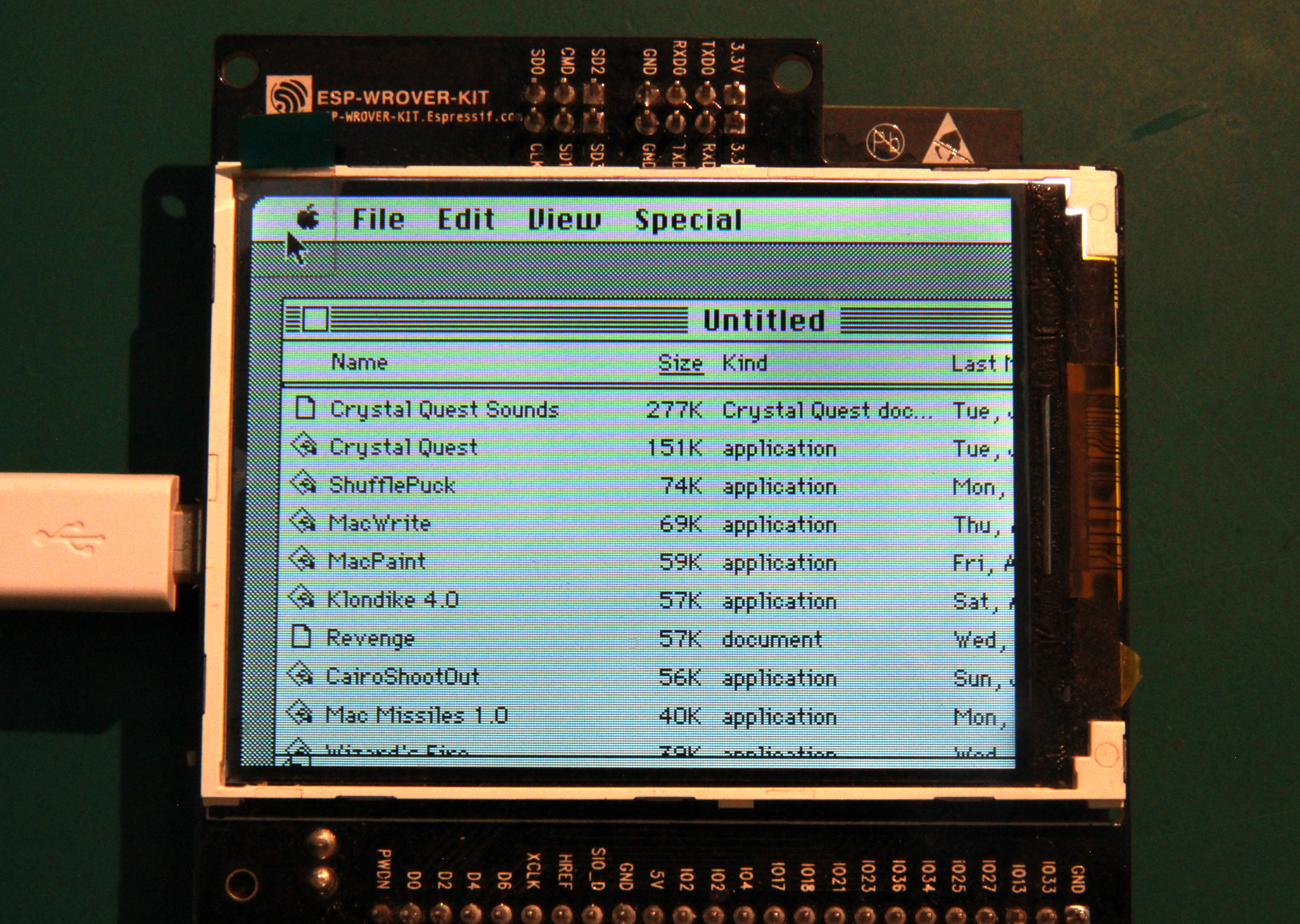
After some tweaking, the Mac emulator actually ran fairly well on this board; it usually comes pretty close to the 7.8MHz the Mac Plus normally runs at. (Actually, 7.8MHz would be slightly faster than a Mac Plus; because the frame buffer and sound system in the real thing eat up some of the memory cycles, the actual effective frequency could be as much as 35% lower.)
Obviously, getting the emulator working on a devboard is a nice step along the way, but in the end, the thing needs to run on the screen that I bought, not the devboard screen. And hold on a second, the devkit screen is 320x240 and cuts off a fair chunk of the Mac screen. The display I intend to use is 320x320 and as such only larger vertically: how am I going to get the 512x342 Mac screen displayed on it?
There’s one way to put 512x342 pixels onto a 320x320 screen, and that is scaling. Effectively, you take an image, then squish it to make it smaller, then you display it. However, scaling can be done in multiple ways and especially with a black-and-white image generated by an OS that assumes every pixel it set results in a clearly distinguishable point of light on the screen, there are multiple ways to do it badly. Effectively, I would like to lose as little resolution as possible. This means I needed to increase the resolution of my OLED.
But how do you do that? I can hardly open up the OLED screen and squish some more pixels in there. However, I don’t need to; the OLED display already has three times as many pixels as advertised. The reason for this is that the OLED screen is a color one: for each virtual ‘pixel’, it has a red, a green and a blue subpixel. Additionally, in this specific screen, the subpixels are laid out in triangles. To illustrate this, here’s a close-up of the screen, with three pixels lit:
![]()
As you can see, the pixels are triangle-shaped sets of three subpixels; depending on the column they are on, the triangles either point up or down. This effectively means that our subpixel screen resolution is a nice 480 x 640 pixels instead. While still not entirely adequate for displaying 512x342 pixels, the difference is so small that with a small bit of well-chosen scaling the display looks as readable as an 1.63" display showing a GUI meant for a 9" screen will ever be:
Enclosure
So now I had a display, software that could emulate a Macintosh Plus fairly well, plus a microcontroller it could run on. What’s still missing? A nice box to put it in, obviously!
I decided to 3d-print one on the nice Formlabs 1+ SLA printer my work has. To do this, I first needed a model. I wanted to build one from scratch. Obviously, to do this it would be best if I had a real Macintosh Plus at my disposal. I actually have one in my posession, but it was half a continent away… Luckily, I could get my hands on the next best thing: some kind soul uploaded the dimensions of an original Mac 128K (which has almost the same case as the Plus) to the iFixit wiki.
I still do all my 3d modeling in OpenScad, and after some sweating and cursing to get all the curves looking like they should, I had a nice model of an 1-to-6-scale Mac. 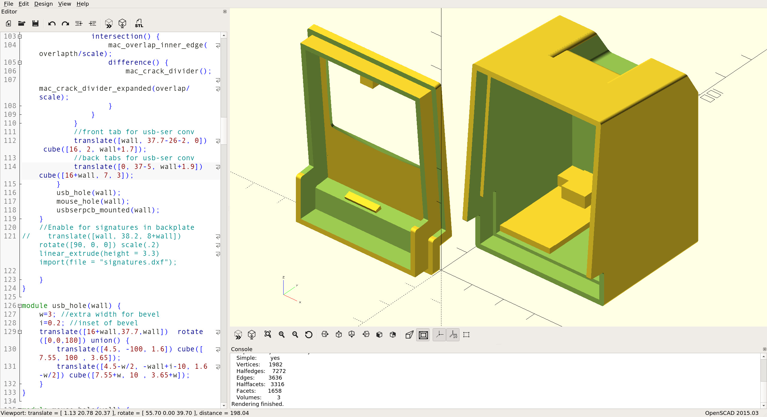
The mouse was also created from the iFixit images, but because it needed to fit the (relatively large) optical mouse sensor, unfortunately it couldn’t be scaled to 1/6th of the real thing. The scale is more like 2/5th, making it seem somewhat large next to the tiny Mac but also making it way more usable for non-scaled-down human fingers.

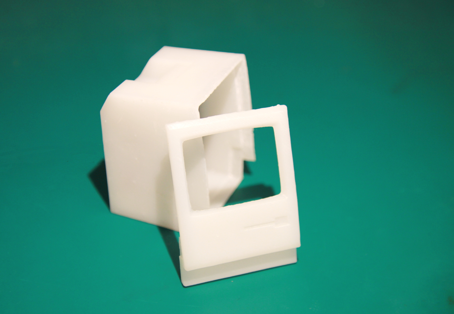
So now all that remained was to print the thing. I exported the design as various STL files and used the Formlabs 1+ to print them. This went fairly well, althought the resin was somewhat old so I put a few more supports than the default in to make sure I wouldn’t get a mis-print. The end result came out pretty nice; the only regret I have is that I didn’t put locking clips for the two halves in the design. I eventually worked around that by just sealing the two halves together using a drop of superglue.
Result
So, I had all the parts and I just needed to click them together. The PCB slots in the front of the case, where a few clips hold it in. The usb-to-serial converter, used as an upload mechanism and a power supply, slot into the back bit and is also held by a few clips. I forgot to make something to hold the speaker in, but some superglue can easily affix it inside the case. Finally, the mouse is connected using a bundle of thin wires. (And yes, they kind-of clash with the color scheme… as soon as I find a nicer, thin multi-core cable I’ll replace it with that.)
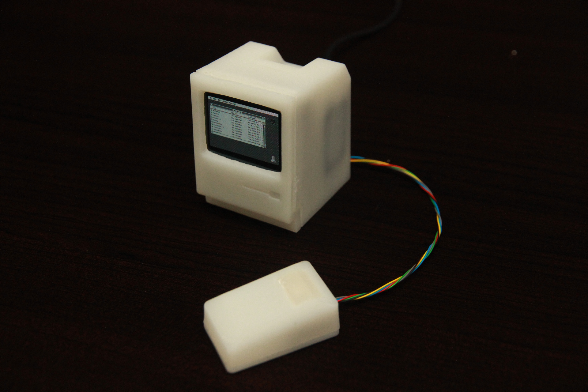
Now, when designing things on a computer in order to have them materialize in full later on, like what happens when you finally receive those PCBs from the factory or when your 3d-printer finishes printing that design you worked for weeks on, is the scale of the thing. Obviously, I knew that all sizes would be 1/6th of a real Mac, but only when everything was put together and I saw the thing in real life, the implications of this showed. The Mac truly is tiny!


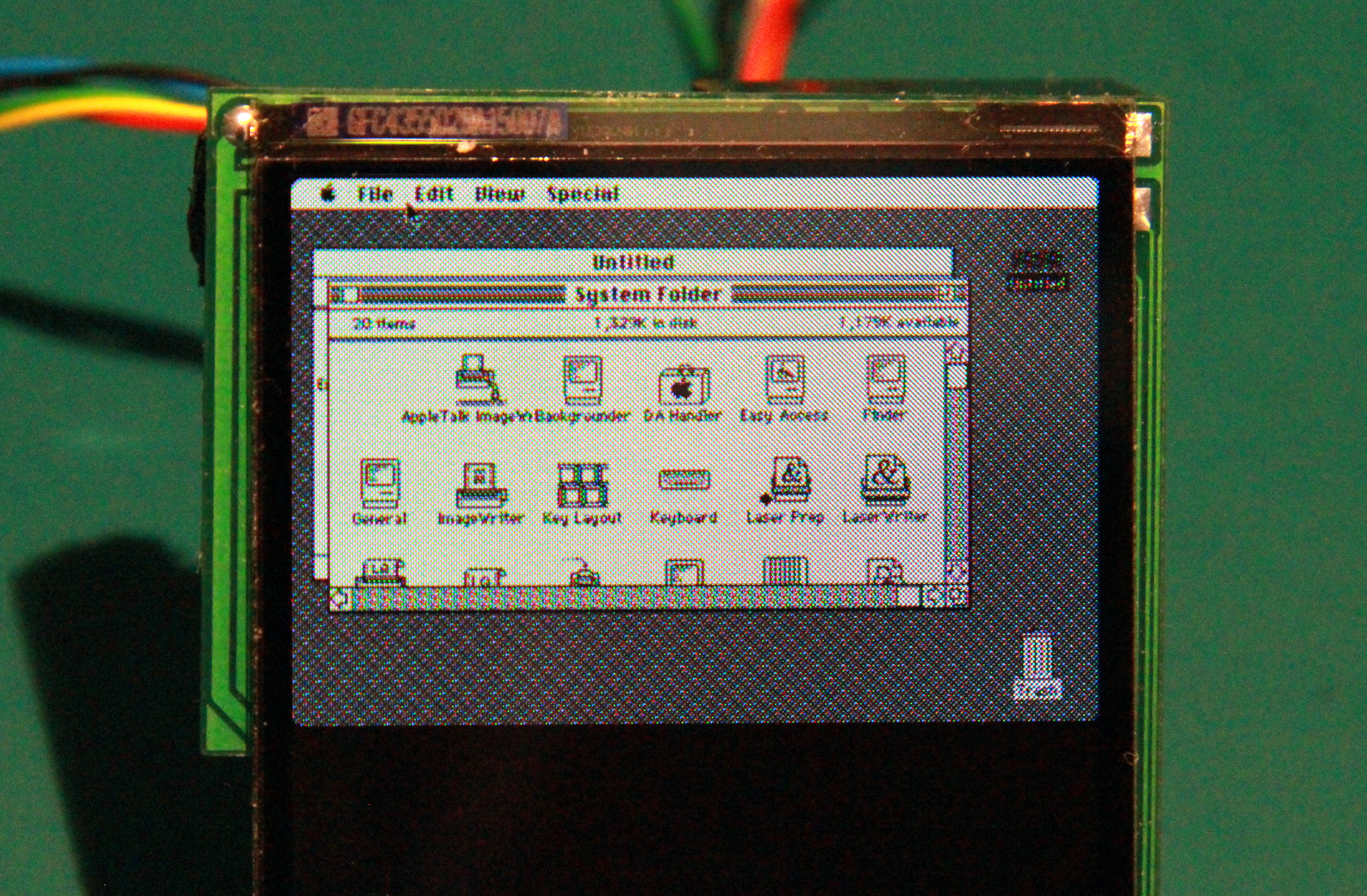
And even with its minute size and lack of a keyboard, it does run most of the things the Mac is well-known for. Here is a demonstration. The first 20 seconds are the memory test, and I know from experience the test lasting this long is not a bug: it took our original Mac Plus that long to boot as well after we upgraded it.
So, what good is this Mac Plus in the end? Admittently, while I had a blast making it, without a keyboard it can’t really serve a real purpose. Also, it has no connectivity to speak of: I planned to make it do AppleTalk over WiFi, but I failed because of some weirdnesses I couldn’t emulate right in the serial controller chip of the original Mac. Still, with the project finished in the state it is, I can finally live my lifelong dream to have a Mac on my desk displaying the original After Dark flying toasters:

As always, this project is open-source, and the PCB artwork as well as the case design and the firmware are up on Github. Everything is licensed under the Beer-Ware license so you can mostly do with it what you want. If you ever use it in something, I’d really appreciate a [note](http://spritesmods.com/?art=contact&af=Miniature Macintosh Plus), however.